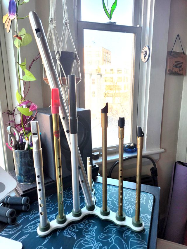
A 3D Printed Irish Whistle Stand
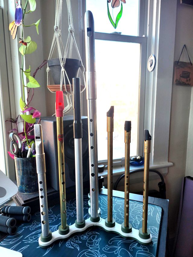
Irish whistles¹ each play a limited set of pitches and therefore come in a particular key: you can have a D whistle, a G whistle, etc. If you’re a whistler, you might have a number of whistles that you switch between. Over the past several months I’ve been working on a design for a portable 3D printed whistle stand, to hold all these many whistles, as a Christmas gift² for my partner who plays the whistle.
This is the most engineered (over-engineered, perhaps?) design I’ve worked on and it’s still not perfect; I’ll get into the flaws later. Emma sketched out the original design concept to me one day – intending it to be made out of wood – but I took the concept and iterated on it in secret to produce this 3D printable design.
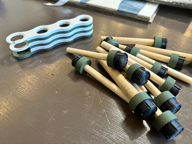
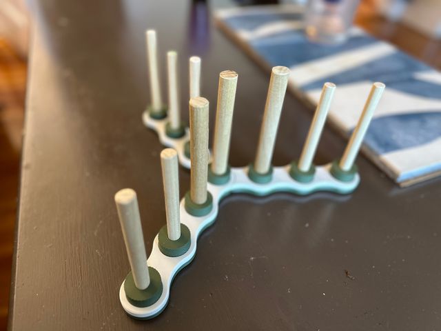
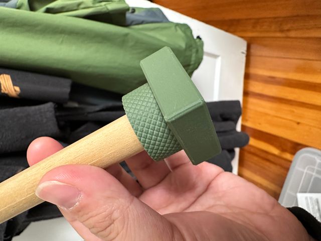
It’s made up of three legs for the base, each with four holes that the round “dowel mounts” snap into. The dowels are made of wood, held into the mounts by friction. It’s designed to come apart so that it can be taken to a session, concert, or on travel. The parts are fairly large altogether, so it’s not pocket-sized (especially if you include the size of the whistles), but it’s adequate for taking on the go. The legs snap together with magnets and the dowels are carried loose.
The Connector
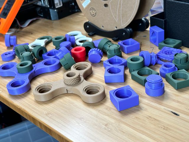
Designing the connector between the base and the dowels took the bulk of my design time. I must have gone through testing 50 some odd iterations trying different designs, then tuning different parameters of each concept. I started with a screw thread design, took a detour through a twist-and-lock mechanism, before finally settling on the annular snap joint pictured in profile here:
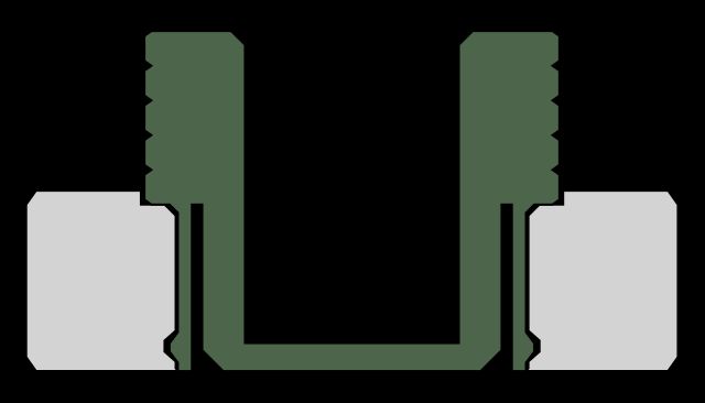
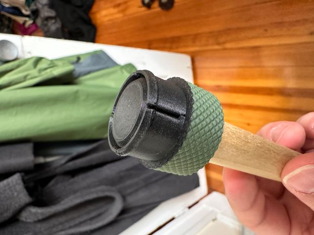
Once I settled on the annular snap joint, I discovered through stress testing that the tabs on the joint broke easily. One downside of 3D printed components is that they are printed from the bed up³ layer by layer. Layers fuse together imperfectly, so 3D prints tend to be weak along the layer lines. It turned out this was especially true of the matte green filament that I wanted to use for this part, which was disappointing because I preferred it aesthetically for this design to some stronger filaments I tested! Fortunately I realized I could print the visible cap in the matte, but switch midway through to a stronger black filament – which would be hidden when the part was engaged.
Mid-Print Insertions
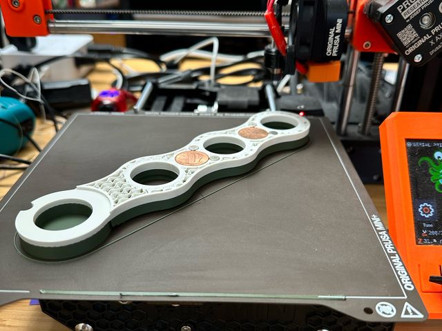
I wanted to add weights to the legs, to increase the stability of the whole apparatus and give it a more premium feel. I added cavities to the model into which I could insert stacks of pennies mid-print⁴⁵. The result was that each leg required three pauses mid-print:
- a pause to insert magnets at the bottom (you have to use a dab of superglue to hold magnets in place – otherwise they run the risk of being drawn upward to the magnetic components of the printer hotend),
- a pause at the halfway mark to change from the green filament to the white (this was optional, but I like the bicolor look – and it provides a visual cue to prevent trying to put the base together with parts inverted), and
- a pause at the top to insert the top magnets and the pennies.
Future Work
While I have delivered the gift (partially as an attempt not to keep designing for months without knowing how well it works already) there’s already areas I’d like to improve in future versions. I’ve made it clear to Emma that the gift is the design, not the physical object, and we will continue to print further iterations of it until it meets her needs.
Connector stability
I set out trying to design a connector that would:
- hold fast and, in particular, be able to hold the middle of the base where all three parts join together, and
- be quick to assemble and disassemble, even if you have to do ten of them at a time,
My annular snap joint achieves criteria 2, but only partially achieves criteria 1. The center connection is fairly unstable with a whistle on it and I’ll have to improve it in future iterations – especially because one of Emma’s pieces of feedback upon receipt was that it would be nice to be able to grab the entire assembly from the center to move it once the whistles are on.
It’s possible I need a stronger connector design – or possibly even just for the center piece. One of my original goals was to have all of the posts be interchangeable, but I think it would be reasonable to have a slightly different design for the center post. Perhaps I’ll give the twist-and-lock connector another go.
Top finish
3D printing is done line by line, and I spend a lot of time trying to compensate for the visible extrusion lines to produce objects that are attractive and aesthetically polished. I tried a few different methods of finishing the top and finally settled on “ironing” in which the hot printer nozzle makes a final pass over the top layer at a fraction of the extrusion width to smooth out the lines. It also extrudes a small amount of filament as it goes to fill in micro-gaps in the surface.
This is fairly effective, but, for whatever reason, there are some noticeable uneven bits in the finish. I’d like to dial in my ironing settings – or come up with a different method of finishing the top that I prefer.
Different shapes
The three-legged design came from Emma’s original drawings (with my own aesthetic flourishes) but as I’ve been designing this I’ve been considering other shapes it could take, some of them potentially more stable or compact. A simple square with 3×3 mounts could take the same connectors but be somewhat more compact. Or perhaps there’s a hinged base design that could fold up trifold-style, making it compact to travel, compact when laid out on a surface, and unfussy to assemble.
Of course, whether or not I explore these depends on whether there’s interest in them – whether from Emma or someone else. I’m not a whistle player myself and have no need for a million different whistle stands – or even one.
Details
The model was designed in OpenSCAD – which some designers consider a form of masochism⁶ – using the BOSL2 library – which makes it slightly less masochistic. I highly recommend it.
- The code is available on GitHub
- Pregenerated models in a variety of configurations (different amounts of tolerance, different numbers of posts) are available on Printables.
Sometimes called tin whistles (despite rarely being made of tin) or penny whistles (despite never being made of pennies). ↩︎
You may note that it is now March, famously not the month Christmas is in. ↩︎
At least for common “fused deposition modeling” (FDM) printers which lay plastic down out of a nozzle. Resin printers, by contrast, print downward from a hanging plate as it ascends up out of the liquid resin. ↩︎
As far as I can tell this is not illegal and in fact even destroying US coins is not illegal so long as you do it in small quantities and don’t aim to profit off of the material value of the metal, which is why those novelty penny press machines are permissible – though I’m not even destroying them here. N.b., this is not true for the coins of all countries. ↩︎
There’s another joke about penny whistles in here somehow. ↩︎
Maybe this will be the subject of a longer post, but very few designers consider functional programming the ideal way to model 3D objects and OpenSCAD’s language is not exactly the most ergonomic. Industrial design standard features like fillets and chamfers require a lot of additional thinking through to achieve. But it has advantages as well: it tickles my programmer brain and models come out of it “parameterized” – easy to fine tune particular features or measurements on the fly to produce new versions or multiple variations. ↩︎